WSC Abstract 5 Using of Asteroids 6-4-02
World Space Congress-2002.IAC-02-S.6.04
Employment of Asteroids for Movement of Space Ships and Probes
Alexander Bolonkin,
Senior Research Associate of NRC in Eglin AF Base.
Tel/Fax 718-339-4563, E-mail: aBolonkin@juno.com
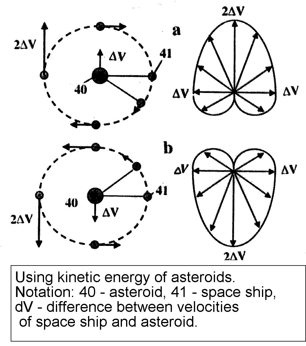
Fig.1. Using kinetic energy of asteroid. Notations: 40-asteroid, 41-space ship, V = difference between velocities of space ship and asteroid.
Abstract
At present, rockets are used to change the trajectory of space vehicles. This method is very expensive and requires a lot of fuel, which limits the feasibility of space stations, interplanetary space ships, and probes. The author offers a revolutionary method for changing the trajectory of space ship and probes. This method uses the kinetic or rotary energy of asteroids, meteorites and other space bodies (small planets, natural and artificial planet satellites, etc.) by cable connection to a space body. The method can increase (decrease) ship speed up to 1000 m/sec (or more) and get any new direction in outer space.
There are many small solid objects in the Solar System called asteroids. The vast majority are found in a swarm called the asteroid belt, located between the orbits of Mars and Jupiter at average distance of 2.1 to 3.3 astronomical units (AU) from the Sun. Scientists know of about 6000 big asteroids (diameter 1 kilometer or more). Their trajectories are known. There are millions of small asteroids with diameter 3 meters or greater. In addition, there are huge numbers of small asteroids, meteorites, and comets out of the asteroid belt. For example, scientists know about of 1,000 asteroids with diameter greater than 1 kilometer located near the Earth. Every day 1 ton meteorites with mass over 8 kg fall on the Earth.
The author’s idea is a utilization of the kinetic energy of the asteroids or meteorites for change of trajectory and speed of space ships (probes). Any space bodies more than 10% of ship weight may be used.
The theory, method and facilities for changing the trajectory (direction and speed) of space ships and probes are presented.
The theory, computations and estimations show the possibility of making this method a reality in a short period of time (see attached projects). The space vehicle recognizes a speed and direction of asteroid by locator or telescope in distance hundreds km, computes the benefit of using its energy, and corrects its own trajectory to intercept. At intercept, the space apparatus temporarily connects to the asteroid by anchor and rope, gets needed speed and direction, disconnects from the asteroid, and spools rope for next connection.
The capability to change the trajectory and speed of the space ship by an asteroid is shown in project. The space ship could obtain a maximum additional speed equal to two times the speed difference between the space ship and asteroid. If the length of the connection rope is in changed, the speed of the space ship could change by more than double the speed difference, or the ship can get additional energy. If the asteroid is rotating, the space ship can obtain additional speed. The additional speed from one asteroid is limited by the mass of the rope. For an additional speed of 1000 m/sec, the mass of rope would be 4.5% the mass of the space apparatus (cable using made from currently manufactured artificial fibers). For an additional speed of 2000 m/sec, the mass of rope would be 18% of the space apparatus mass.
Since there are a large number of asteroids and small planets in the universe, a space ship could fly long distances without propulsion. For example, Mars has 2 small satellites (Moons), Jupiter has 8 small satellites, Saturn has 18 satellites, Uranus has 15 satellites, and Neptune has 8 satellites.
File: WSC Abstract 1a corrected 6-5-02
World Space Congress. IAC-02-V.P.07
Inexpensive Cable Space Launcher of High Capability
Alexander Bolonkin
Senior Research Associate of NRC at Eglin AFB.
Tel/Fax USA 718-339-4563.
E-mail: aBolonkin@juno.com, http://Bolonkin.narod.ru
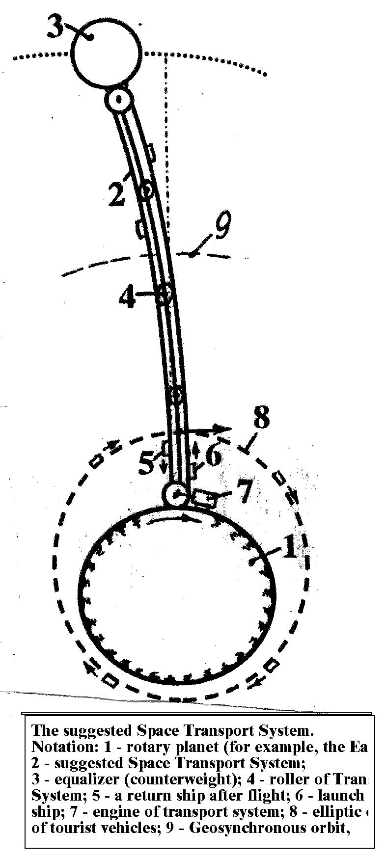
Fig.1. The suggested Space Transport System. Notations: 1 – Rotary planet (for example, the Earth); 2 - suggested Space Transport System ; 3 - equalizer (counterweight); 4 - roller of Transport System; 5 - launch space ship; 6 - a return ship after flight ; 7 – engine of Transport System; 8 – elliptic orbit of tourist vehicles; 9 - Geosynchronous orbit.
Abstract
Author proposes suggests method of flights to outer Space, described in book "Non Rockets Flights in Space", which is prepared for publication.
The author developed theory and has proposed a new revolutionary transport system for delivery of payloads and people into space and for accelerating a space ship for interplanetary flight. This method uses energy of downward moving loads and the rotary energy of the planet.
A proposed centrifugal space launcher with a cable transport system is shown in figure. The system includes an equalizer (or space station) located in a greater than geosynchronous orbit, an engine located on Earth, and the cable transport system having three cables: a main (central) cable of equal stress, and two closed-loop transport cables, which include a set of mobile cable chains connected sequentially one to other by rollers. One end of this set is connected to the equalizer, the other end is connected to the planet. A conventional motor located on the planet drives the transport system. When payloads are not being delivered into the space, the system may be used to transfer mechanical energy to the space station or to the load cabin.
The launching is released by disconnecting space load (tourist cabin, satellites) from cable below the geosynchronous orbit. The load will have elliptic orbits and may be connected back to the transport system after some revolutions when the space ship and cable are in same position. If it is a low earth orbit satellites then it will use a brake parachute to have their orbit closed to a circle .
The space probes released higher than geosynchronous orbit will have a hyperbolic orbit, to fly to other planets. They can connect back to transport system when ship is returned.
Most space payloads, like tourists, must be returned to Earth. When one container is moved up the cable, then another container is moved down. The work of lifting equals to the work of descent, except small loss in the rollers. The proposed transport system lets us fly into space without spending enormous energy. This is reason why the method and transport system are named a "Free Trip".
The project uses the whisker cable with ratio stress/density of 4000 km (nanotubes have this ratio up 100,000 km). The equalizer weighs 518 tons and is located at 100,000 km. The three cable have diameter from 0.73 mm to 1.33 mm each.. They can handle 10 tons. The passenger vehicle has 27 seats and a mass of 3 tons. Every 2 hours the vehicle is lifted to on altitude of 22,000 km , is disconnected to make 4 four revolutions around Earth (minimum altitude 200 km) in during one day, to connect back to transport system. It dissents, and lifts the next vehicle. In total 24 vehicles per day are moved in both direction. The transport system can serve about 100,000 space tourists annually. The transportation cost is $160/man or S1.27/kg. The initial small installation for delivering 50 kg load will cost $220 million. Further development is made by self-financing. The total delivery capability of proposed Transport System is 12,000 tons annually to Earth orbit or 2000 tons to Mars.
The author has solved most problems and is prepared to discuss the problems with serious organizations that want to research and development these innovations. Patent application is 09/789,959.
Abstract 10 of Space Tower 4-30-02
World Space Congress. COSPAR02-A-02228, C-018.
Optimal Inflatable Space Towers of High Height
Alexander Bolonkin
Senior Research Associate of NRC at Eglin AFB
1310 Avenue R, #6-F, Brooklyn, NY 11229, USA
T/F 718-339-4563, E-mail: aBolonkin@juno.com, http://Bolonkin.narod.ru
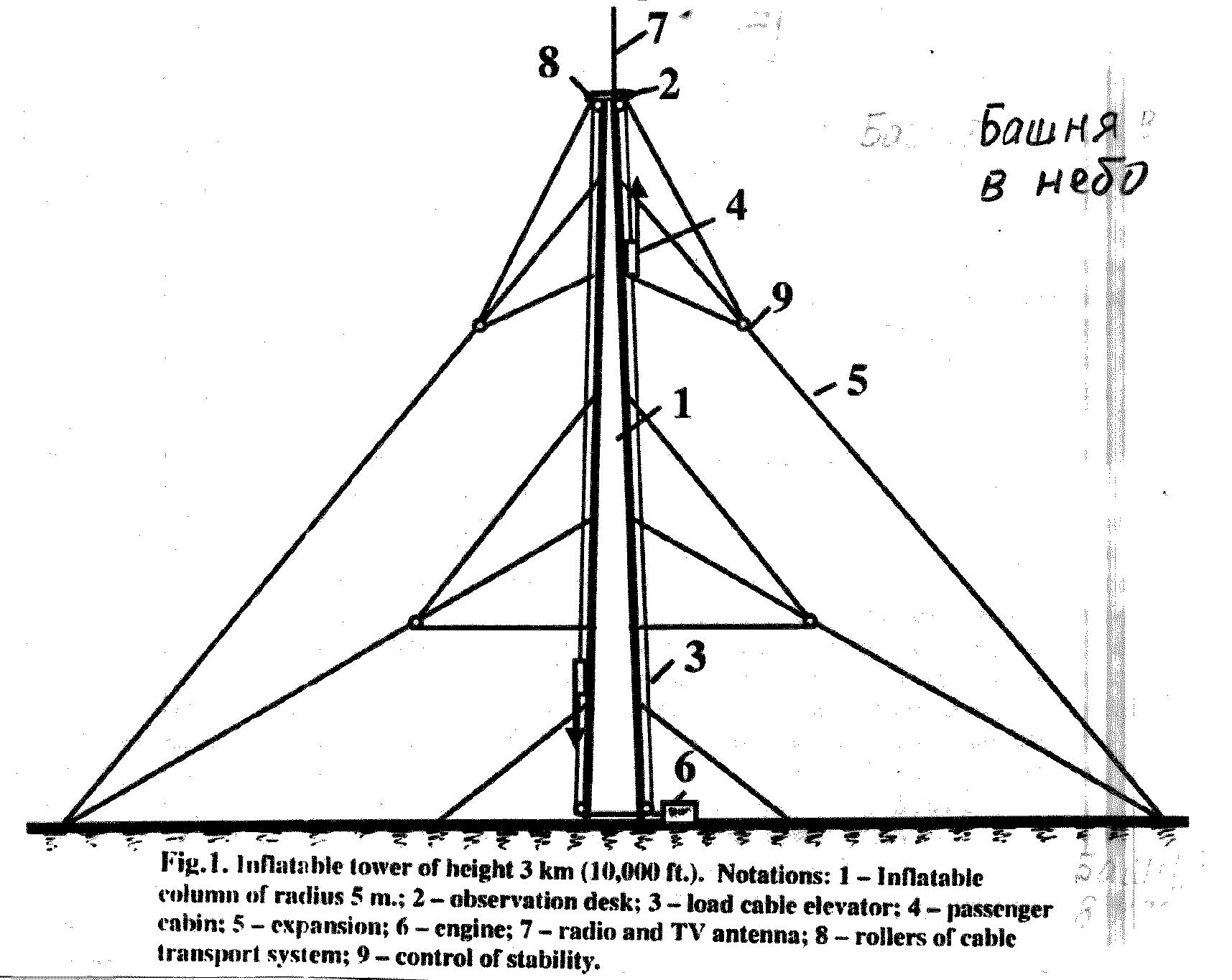
Fig.1. Inflatable tower of height 3 km (10,000 ft.). Notations: 1 – Inflatable column of radius 5 m.; 2 – observation desk; 3 – load cable elevator; 4 – passenger cabin; 5 – expansion; 6 – engine; 7 – radio and TV antenna; 8 – rollers of cable transport system; 9 – control of stability.
Abstract
Author provides theory and computations for building inflatable space towers up to 3, 30, 100 km in height. These towers can be used for tourism; scientific observation of space, earth’s surface, weather, top atmosphere, as well as for radio, television, and communication transmissions. These towers can also be used to launch space ships and Earth satellites.
These projects are not expensive and do not require rockets. They require thin strong films composed from artificial fibers and fabricated by current industry. Towers can be built using present technology. Towers can be used (for tourism, communication, etc.) during the construction process and provide self-financing for further construction. The tower design does not require work at high altitudes; all construction can be done at the earth’s surface.
The transport system for this tower consists a small engine (used only for friction compensation) located at the earth’s surface. The tower is separated into sections and has special protection mechanism in case of a damage.
Problems involving security, control, repair, and stability of the proposed towers are addressed in subsequent publications. The author is prepared to discuss these and other problems with serious organizations desiring to research and develop these projects.
Project 1. A simple air tower of 3 km height (Base radius 5 m, 15 ft. K=0.1). This inexpensive project provides experience in design and construction of a tall inflatable tower, in their stability. The project also provides funds from tourism, radio and television. The inflatable tower has height 3 km (10,000 ft). Tourist will not need a special suit or a breathing device at this altitude. They can enjoy an Earth panorama in radius up to 200 km. The bravest of them could experience 20 seconds of free-fall time followed by 2g overload.
Results of computations. Assume the additional air pressure is 0.1 atm, air temperature is 288oK (15oC, 60oF), base radius of tower is 5 m, ratio of tensile stress to density of gas-bag is K=***=0.05 -0.3. Take K=0.1 (*=180 kg/mm2, *=1800 kg/m3). If tower cone is optimal, the tower top radius must be 4.55 m. The maximum useful tower top lift is 46 tons . The cover thickness is 0.087 mm at base and 0.057 mm ai top. The outer cover mass is only 11.5 tons. If we add light internal partitions, the total cover weight will be about 16 - 18 tons (compared to 3 millions tons of the 553 m tower at Toronto). Maximum admissible bending moment versus altitude ranges from 390 ton*meter (at base) to 210 ton*meter at the tower top.
Economical efficiency. Assume the cost of tower is $5 million, life time is 10 years, annual maintenance $1 million, number of tourists at the tower top is 200 (15 tons), time at top 0.5 hour, the tower is open 12 hours per day. Then 4800 tourists will visit the tower per day, or 1.7 million per year. Unit cost of one tourist is (0.5+1)/1.7=1 $/person. If a ticket costs $9, the profit is 1.7*8=$13.6 million per year. If a drop from tower (in special cabin, free-fall (weightlessness) time is 20 sec, followed by overload of 2g) will cost $5 and 20% of tourists will take it, the additional profit will be $1.7 million.
Abstract 11 Moon Transport System for WSC COSPAR 2002
World Space Congress-2002. COSPAR02-A-02224, B-037.
NON ROCKET EARTH-MOON TRANSPORT SYSTEM
Alexander Bolonkin
Senior Research Associate of NRC at Eglin AFB
1310 Avenue R, #6-F, Brooklyn, NY 11229 USA
T/Fax 718-339-4563;
E-mail: aBolonkin@juno.com; http://Bolonkin.narod.ru
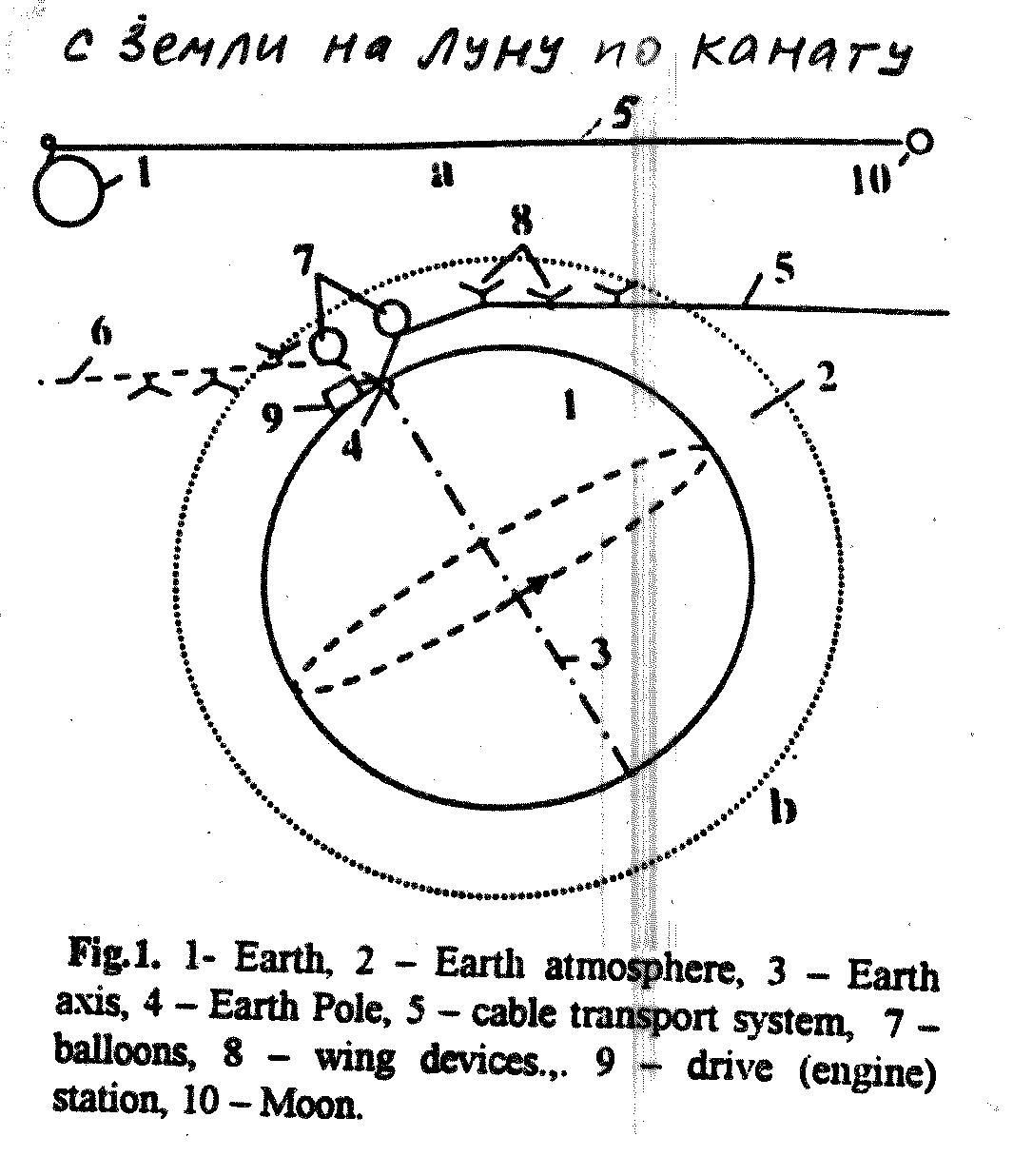
Fig.1. 1- Earth, 2 – Earth atmosphere, 3 – Earth axis, 4 – Earth Pole, 5 – cable transport system, 7 – balloons, 8 – wing devices.,. 9 – drive (engine) station, 10 – Moon.
ABSTRACT
Author suggests and researches one of his methods of flights to outer Space, described in book "Non Rocket Flights in Space", which is prepared and offered for publication.
In given report the method and facilities named "Bolonkin Transport System" (BTS) for delivering of payload and people to Moon and back is presented. BTS can be used also for free trip to outer Space up at altitude 60,000 km and more. BTS can be applying as a trust system for atmospheric supersonic aircrafts, and as a free energy source. This method uses, in general, the rotary and kinetic energy of the Moon.
The manuscript contains the theory and results of computation of special Project. This project uses three cables (main and two for driving of loads) from artificial material: fiber, whiskers, nanotubes, with the specific tensile strength (ratio the tensile stress to density) k=s/g=4*10^7 or more. The nanotubes with same and better parameters are received in scientific laboratories.
. The upper end of the cable is connected to the Moon. The lower end of the cable is connected to Earth Pole Station or to an aircraft (or buoy), which flies (i.e. glides or slides) in Earth atmosphere along the planet’s surface. The Pole station (aircraft and Moon) has air balloons, wing devices, and devices, which allows the length of cables to be changed. The devices would consist of a spool, motor, brake, transmission, and controller. The facility could have devices for delivering people and payloads to the Moon and back using the suggested Transport System. The delivery devices include: containers, cables, motors (at the Earth), brakes, and controllers. If the suggested Transport System is used only for free thrust (9 tons), the system can pull the three supersonic transport (passenger) aircraft or produces up to 40 millions watt energy.
The Moon’s trajectory has an eccentricity. If the main cable is strong enough, the Moon may be used for free lifting (traveling) a payload (men cabins) to an altitude of about 60,000 kilometers every 29 days. For this case, the length of the main cable from the Moon to the container does not change and when the Moon increases its distance from the Moon to the Earth, the Moon lifts the space ship. The cabin could land back on the planet at any time if it is allowed to slide along the cable. The Moon’s energy can be used also for an inexpensive trip (passenger system) around of the Earth by having the moon "drag" an aircraft around the planet (using the Moon as free thrust engine) with supersonic speed, about 440 m/s (Max Number is 1.5).
Project. Free Trips to the Moon. The following is some data estimating the Moon Transport System which provides an inexpensive payload transfer between the Earth and the Moon. The system has three cables. Every cable can keep the force 3 tons. Material of cable has specific strong k=4*10^7. All cables have cross-sectional areas of an equal stress. A minimal cross-sectional area of cable is 0.42 mm2 (diameter 0,73 mm) and maximum cross-sectional area is 1.9 mm2 (1.56 mm). The mass of the main cable is 1300 tons. The total mass of the main cable plus the two container cables (for delivering a mass 3000 kg) equals 3900 tons.
An unlimited and inexpensive means of the payload delivery between the Earth and the Moon could be obtained. An elapsed time to the Moon trip with a speed of 6 km/sec would be about 18.5 hours. The annual deliver capably is 1320 tons (or 10,000 tourists) in every direction. If one cable will be damaged two others will be used for safe people and repairing.
The author has also solved additional problems, which appear in these projects and which can look as difficult for the proposed space transportation technology.
The author is prepared to discuss the problems with serious organizations, which want to research and develop these projects.
Abstract 12 Earth-Mars Transport System for WSC COSPAR 2002
Wold Space Congress –2002. COSPAR02-A-02226, B-057
NON-ROCKET EARTH-MARS TRANSPORT SYSTEM
Alexander Bolonkin
Senior Research Associate of NRC at Eglin AFB
1310 Avenue R, #6-F, Brooklyn, NY 11229 USA.
T/Fax 718-339-4563
E-mail: aBolonkin@juno.com; http://Bolonkin.narod.ru
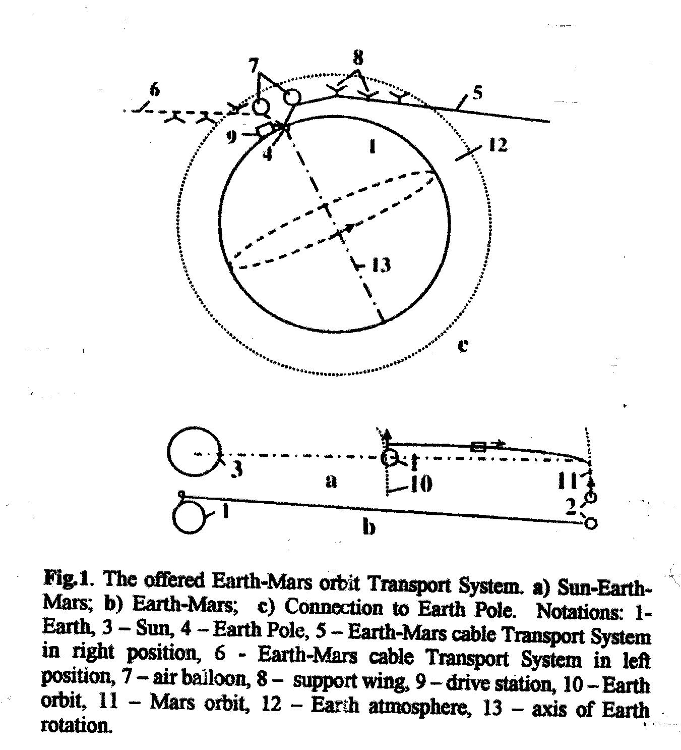
Fig.1. The offered Earth-Mars orbit Transport System. a) Sun-Earth-Mars; b) Earth-Mars; c) Connection to Earth Pole. Notations: 1- Earth, 3 – Sun, 4 – Earth Pole, 5 – Earth-Mars cable Transport System in right position, 6 - Earth-Mars cable Transport System in left position, 7 – air balloon, 8 – support wing, 9 – drive station, 10 – Earth orbit, 11 – Mars orbit, 12 – Earth atmosphere, 13 – axis of Earth rotation.
Abstract
Author suggests and researches one of his methods of flights to outer Space, described in book "Non Rocket Flights in Space", which is prepared and offered for publication.
In given report the method and facilities named "Bolonkin Transport System" (BTS) for delivering of payload and people to Mars and back is presented. BTS can be used also for free trip to outer Space in other planets.
The manuscript contains the theory and results of computation of special Project. This project uses three cables (main and two for driving of loads) from artificial material: fiber, whiskers, nanotubes, with the specific tensile strength (ratio the tensile stress to density) k=s/g=15*10^7 or more. The nanotubes with same and better parameters are received in scientific laboratories. Theoretical limit of nanotubes of SWNT is about k=100*10^7.
The cable has a length approximately equals the minimal distance from Earth to Mars. The upper end of the cable located near Mars orbit. The lower end of the cable is connected to Earth Pole or an aircraft (or buoy), which flies (i.e. glides or slides) in Earth atmosphere along the planet’s surface. The aircraft has devices, which allows the length of cables to be changed. The device would consist of a spool, motor, brake, transmission, and controller. The facility could have devices for delivering people and payloads to the Mars and back using the suggested Transport System. The delivery devices include: containers (men cabins, space ships), cables, motors, brakes, and controllers. The BTS can use the rotary and kinetic energy of Earth and Mars for moving of aircraft. The lower aircraft can temporary land to Earth surface for loading and repairing. The space cabin, when it locates at upper cable end, has small rocket engine for maneuverability and landing on mars surface. The Earth aircraft has speed about 440 m/sec (1584 km/hour) and may be also used as transport vehicle.
Every two years the Mars came up to minimal distance to Earth. About two months can be used for delivery people and loads to Mars. The space ships advance to move to upper end of BTS. When Mars arrives the vehicles land on it surface, the people work on Mars 1-1.5 months. After the space ships started back to Earth. In during the Mars living, the people can fly from one place to others with speed about 230 m/sec (include Mars round trip on low altitude) by their space ship. It does not request the rocket fuel. They explore the BTS.
Project. Earth-Mars non-Rocket Transport System. The following is some data estimations of the Mars Transport System which provides an inexpensive payload transfer between the Earth and the Mars. The system has three cables. Every cable can keep the force 3 tons. Material of cable has specific strong k=20*10^7. All cables have cross-sectional areas of an equal stress. A ratio of maximum cross-sectional area to minimum cross-section area of the cable is 4.4 . The mass of the main cable is 35 thousand tons. The total mass of the main cable plus the two container cables (for delivering a mass 3000 kg) equals 110 thousand tons. An unlimited and inexpensive means of the payload delivery between the Earth and the Mars could be obtained. If one cable will be damaged, two others will be used for safe people and repairing.
The author has also solved additional problems, which appear in these projects and which can look as difficult for the proposed space transportation technology.
The author is prepared to discuss the problems with serious organizations, which want to research and develop these projects. Patent application is 09/789,959 USA.
next page
Contents of the main page
Число посeтитeлeй с 17 ноября 2002г.